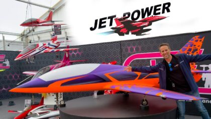
Descriptions:
SAB Lizard 2: Making STAR WARS 3D style!
Beschreibung zum Video:
Part 2 of the build for my SAB Lizard. If you didn’t see Part 1, go check it out here and then come back!
Subscribe on Youtube: Martin Pickering, click here
Freitag – Newsletter zu allen aktuellen Videos der Woche aus 17 Channels, jetzt anmelden!
Vollständiger Text aus dem Video: SAB Lizard 2: Making STAR WARS 3D style!
Hinweis: Text aus der automatischen Spracherkennung aus dem Video ist allgemein bekannt ungenau!
Welcome to my second video on the SAB Lizard. If you didn’t check out the first one make sure to do so now, we installed pretty much all the servos as well as making a really epic intro to SAB, where they came from and how they’ve taken the jet scene by storm. So with all that said let’s continue the build and get this thing in the sky. Before we get started, a lot of you probably already know that I’ve relied very heavily on Electron Retracts for all of my landing gear requirements, they have a product that has my full confidence and has never let me down. On this occasion however the guys at SAB were good enough to throw in a kit of their own landing gear to test in my very own Lizard so let’s get them installed and see how they perform. I’ve already installed one landing gear before making the video just to check how everything works, lines up and fits and I’m very pleased to say that it was very quick to do, everything worked just as you would want it to. Just like we saw in the previous video all we had to do was locate all the different numbered bags, all the components and simply screw it all into place very easy very quick. So let’s get the other one in there and we can move on to the next step Oh yeah don’t forget to connect your power lead to your retracts before screwing it into place. If you don’t as I did with my first one you soon realise that once it in place, because the retract is currently closed you can’t actually get your fingers in to make that connection and the only way to open it is by applying power through that connection, anyway back to the build And just like that we’ve installed our second main landing gear. Now I did install those final rubber grommets in a slightly different position on the leading edge of the wheel well as opposed to the top of it where is shown on the manual simply because it’s kind of more out of the way for any kind of debris, oil, smoke or whatever. It also provides a more direct line straight to the electronics so a win-win but that’s just my personal preference. Anyway we’ve got the mains done, time to install the front wheel and keep going. The nose leg actually attaches to the front former of the fuselage. Now because of that we can’t simply mount the retracts onto it because it would be at the wrong angle and it’s not that tall so instead the kit comes with a mounting bracket onto which you mount the retract and then that then simply screws onto the front former so we’re gonna start by mounting everything onto here, so the leg, the servo mounting bracket the whole system and then once we finish four screws attach it to the front and we are finished And that’s the nosewheel installed, now I will stop here and make two points though. The first of which is I wasn’t initially too convinced about the whole idea of having this secured with just four wood screws. I mean it’s supporting the whole weight of the plane on landing, it’s got the whole tray sitting ahead of it as well resting on there I wasn’t too sure however having just gone and installed those four screws and having had to fight with every single one of them to get them into that wood I’m actually now very happy that they’re not going to be going anywhere, the wood is obviously strong enough and thick enough to actually support all of that. I mean I could barely get them in there so no need to change anything. My second point here is that I may have made another small mistake while filming, that did you see it? I’ll tell you what, if you did, leave me in the comments below, see if you got it right. I’ll give you a couple of seconds, one, two, three. Once again just like with the main landing gear I didn’t connect the wires before installing the actual landing gear itself what that means is I couldn’t get my fingers in to get the wire attached to be able to actually operate it and make it go up and down, this is where the same invention that saved me on the mains saved me for the nosewheel and that is just a tube. All I did was slide the wire through the tube and then use that to push it into place so it may have been a small mistake but it was also easily fixed, albeit a little bit of a pain. On to the next part which is the front tray onto which we’re going to mount all of our batteries, our UAT and any other small accessories. Now we do need to glue a few parts together for this and then once that’s done it’s going to screw onto the landing gear mount that we’ve just installed. To assure a good bond I’m going to scratch the surface first a little bit and then I’m going to use epoxy mixed in with carbon fiber. Now this isn’t anything special it’s just the produce of sanding down an old broken propeller, landing gear or anything else that’s carbon And that’s it for the nose section now you saw in that video that I put tape on the underside of the carbon plate before putting the glue in. It’s really important that you follow that step because I didn’t the first time round and it meant that the glue seeps through, clumps about and it also sticks itself to the table so make sure not to skip that step. Anyway with that said, it’s time to move on to the vector system, the bit that makes it a really fun jet, a 3d jet! Time to install the vector and the two servos which are going to control it I’m not making up or installing the pushrods at this moment as I want to wait until I actually have the turbine to make sure that the route that they have is going to be clear and isn’t going to foul on the turbine anywhere. And that’s the fun pipe installed. I did actually have to remove one of those two servos because the four screws holding it in place were a little bit too long and they were coming into contact with the underside of my MKS servo arm which is particularly low profile so all I did was remove them grind them down a little bit and put them back in again. SAB do actually provide some shims to allow you to lift the servo up a little bit for this exact problem so if this happens to you, you could choose to simply install that, it comes in the kit. In my case, as a 3D plane, the lighter we keep it the better, so the fewer components we have, the better as well. So I chose to simply grind down those screws a little bit rather than adding that shim, however both solutions would work perfectly well. That’s it for this video, if you have any comments please leave them in the comments below, leave us a like, subscribe to the channel if you aren’t already and make sure to tune back in soon, when we’ll be installing the rest of the components in this thing as soon as we receive turbine, power box or anything else that we’re missing Thanks for watching, and I’ll see you all in the next one. I’m Martin Pickering and I really hope you’ve enjoyed this video. make sure to come back every Tuesday for a new episode of cool tech tips and tutorials and on Sundays for flying videos and event coverage or hit that subscribe button and the bell that’s next to it in order to receive a reminder when the next video is uploaded Thanks for watching and I’ll see you all in the next one
Für den Inhalt des Videos ist der VideoCreator: Martin Pickering verantwortlich.
#SAB #Lizard #Making #STAR #WARS #style
pickering, source